
The result of buying a “defekt” FSIQ unit from eBay Germany was that I ended up with a huge instrument lying around for months, with little hopes of ever getting it repaired. The RF CONVERTER module had a (unrepairable for me) YIG unit and I managed to get a used, but working, RF CONVERTER module. The analyzer passed now the selftest but showed some issues with calibration. This is how I fixed the A160 IF-Filter module that was at fault.
The IF Filter module
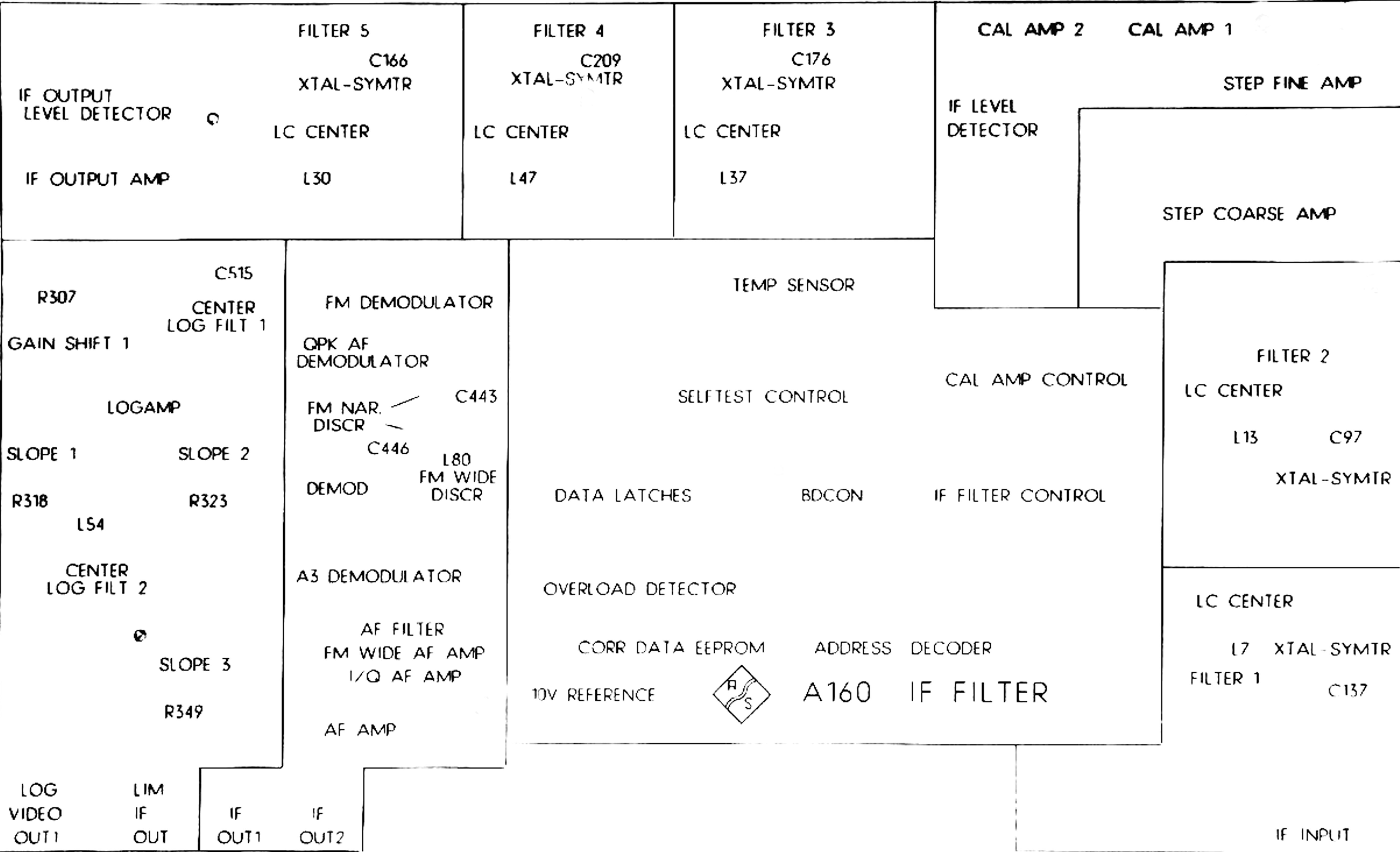
This unit is in charge of filtering the 21.4MHz IF with selected bandwidth and provides two outputs of the filtered IF signal to other modules, does FM/AM demodulation and, of course, measures the level of the IF signal. I was unable to find the service manual for the FSIQ but it is very similar to the FSEA/FSEB and it is possible to find this one. Sadly it does not have schematics but it does have block diagrams and descriptions which are very useful for troubleshooting.
To trace the signals around the module, I took 24MP high-resolution pictures, corrected lens distortions and aligned them so the same vias appear exactly in the same spot. This way you can follow a trace (a bit more) easily by switching from one picture to the other on the screen. You can download the picture byclicking on them, and use your favorite image editor to look around. Note that the bottom image is mirrored so the positions match the top picture, you are looking at the components “from behind” (double click on the picture that opens to see it at 100% size):
Module blocks:
Top side:

Bottom side:

This is what you will see if you stack the photos and change from one to the other, at 100% zoom. Note how the vias stay in the same place:

Calibration Fails
The calibration process is quite detailed and shows on the screen what is being measured at any give momento, and also outputs calibration logs to C:/R_S/INSTR/CAL. Some of the files are binary .DAT files used by the instrument to compensate for deviations, and others are .RES files that are plain text that can be read by humans. If we take a look at the LEVEL.RES file from a failed calibration, we can see that the instrument is finding the bandwidth of most of the crystal filters (1KHz-50KHz) too narrow to be compensated. The 30KHz RBW is 28.2KHz off !!!
It is possible to plot the response and measure the bandwidth of the filters with a VNA, or directly in the analyzer. I confirmed that when the unit it was cold, bandwidth it looked fine (and passed calibration) but after 10-15 minutes, the bandwith was greatly reduced and it failed calibration.
In order to troubleshoot the module, I needed to make it work while being out of the instrument. That meant I had to get longer SMB coax cables, which you can get, and some kind of extender for the power & data bus, which you can’t get…
The eurocard extender
The data bus connector is a DIN 41612 with all three rows (a, b, c) populated for some modules, so I decided to build a extender with the three rows even if the IF module only uses two. It is a simple pin-to-pin adapter with male and female connectors.

The idea is simple but doing it right requires careful planing, since there are no less than 96 pins on each side. I used multi-wire ethernet cable and grouped the colors, the build process looked like this:

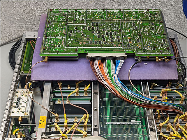
With the extender and a few SMB-SMB coax cables, I could finally turn on the FSIQ with the module outside, this was science fiction for me not very long ago:
Investigation
With the hot air station, it seemed that the sensible are was located in the left lower corner, and the result of warming up slightly that corner was a clear sign of a problem. I captured the VGA output on the following video:
The video starts with a recently booted cold instrument. At 00:03 I blow how air over a particular area of the bottom PCB and you can see how the Bandwidth changes from 29kHz to almost 3kHz only at 00:09. At 00:30 I blow ambient air over the area and the bandwidth goes back to normal.
I had no idea what could be happening to cause that, but when I looked closely at that area…
The culprit component
I first suspected the problem was the crystal, then a capacitor, and finally found that a voltage that controlled the bandwidth was deviating when warm air was applied to that area. I suspected the problem was a OP400 quad op-amp because it was the most sensitive component I could find. But the delay between applying hot air and the bandwidth change pointed to a greater thermal mass than the IC could have. I was right, the problematic component was under that IC, on the other side of the PCB and that was the reason for the delay.
I turned the module upside-down and looked carefully… Oh my God, I could not believe my eyes…

Something that looked like a SOT23 transistor had zero solder on one the pads. I checked that just applying light pressure to that pin I could see the bandwidth abruptly changing back to normal. So simple!
I will save you the effort… Yes, this could be seen on the picture I took of the PCB. It was there in plain sight all the time!!

A bit of solder, everything back together and the instrument works perfectly now. If you kept reading all the way up to this point, thank you.