The 8752A VNA is a wonderful instrument, but it has many years on its back, and you may find yourself with a barely readable, or funky-looking screen due to aged CRT. I have an article dedicated to the CRT to LCD conversion I devised for the HP 8920A. But that was me doing my best to fit a universal composite-to-VGA converter and LCD inside the instrument. www.Simmconnlabs.com offers a LCD conversion kit for the 8752A that includes a custom PCB designed to interface directly with the RAMDAC of the graphics controller of the instrument and a FPGA programmed to decode and rescale the image to the newer resolution with exquisite detail. The biggest flaw of my conversion is the artifacts that result from using basic rescaling algorithms in the VGA-BOX hardware.
This article does not cover the conversion process step-by-step, the instructions provided with the kit are detailed and easy to follow.
Cleaning
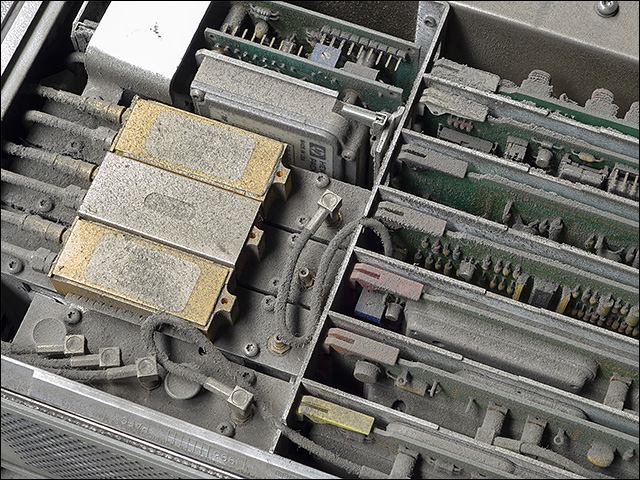
The instrument had the original factory seals, which is always welcome, but that does not mean it will be clean inside. It was VERY dusty:

A quick trip outside with the compressor and, only after the biggest dust cloud my neighbours had ever seen, the colors were back:

External surfaces did not have dust but were dirty and greasy. Water with a just bit of bleach and hydrochloric acid works great for removing this gunky coat on old instruments (always careful mixing that, and only in well ventilated areas):

Installing the kit
The kit comes very well packaged, with two separate PCBs, one that goes over the RAMDAC, and other that goes attached to the nice black metal LCD frame:

With the instrument already open, installation took literally a few minutes only, the step-by-step installation manual is detailed and clear.

Clean and with the LCD in place, the instrument looks simply great!

CAUTION: PROBE POWER SHUTDOWN!
When I thought everything was over, I run the internal tests just to confirm all was ok. And no, it was not:

The message was self-explaining, and yes, there was no -12.6V present on the probe power connector. With no schematics, I traced the signal back to the power supply board, and quickly found an open fuse. I had something similar around so there it went:

What a difference!
I took a few pictures of screens before the upgrade so we can now see the difference side-by-side. I would say pictures don’t do justice to reality, the difference in person is nothing short of amazing. Note the same test pattern appears not only brighter and less funky but also much bigger!:


You can see the right side of the picture appears rescaled and out of place after the upgrade. This only draw my attention with the display test patterns, and I believe it is done on purpose, to show bigger graphics on the screen while retaining the alignment of the menus with the keys to the right of the display. This is great. Nice attention to detail, and something that can’t be done with a universal video signal converter. Believe it or not, this two screens are supposed to be the same (appart from annotations I forgot to enable on the second one):


Final picture of the instrument in all its new glory. I now prefer this 8752A much better than my 8753ES (even after the LED backlight upgrade) because the viewing angle is so much better in the new LCD.

Thanks Xu.
