The HP 6632B is a very nice power supply and it can be had cheap but since it is now quite old the VFD display will very probably have a few segments severly worn-out which makes reading it difficult. Finding a replacement VFD for a reasonable amount is not possible, I believe HP replaced the whole front-panel PCB not just the display module. I thought I could build something to replace that old VFDs.
The original plan was to tap the data going into the VFD controller, but it turns out it uses two VFD drivers from Allegro. The display segments are divided in four groups and each group is on and refreshed one at a time Then the ICs do that again for each segment in each group. I could not find a way for the PIC to keep up with the speed the VDS drivers receive the data. Then I found the controller on the main logic board and the controller on the front panel board talk to each other using a serial protocol. By trial, I was able to understand those messages, make the PIC decode that and drive the OLED module via I2C interface.
Everything that I’ve been able to make appear in the original VFD is captured by the PIC, everything but the following two:
- The SHIFT button indicator, which is kept local to the front panel and does not travel from/to the mainboard.
- The UNREG indicator, because I was unable to put the power supply in the unregulated state without risk of damaging it.
Since I had to use standard 5×7 chars I had to be creative but as you can see it is pretty self explanatory. The RAES string to the right corresponds to REMOTE, ADDRESS, ERROR and SRQ. Note that not all indicators in the original VFD are used in the 6632B, see the user’s guide.

The circuit is very simple, there are only four components involved, the OLED module, a PIC16F88, a 4K7 resistor that goes between the PIC RX pin and the serial bus and a 100nF decoupling capacitor. I built that behind the OLED module using thin wires:

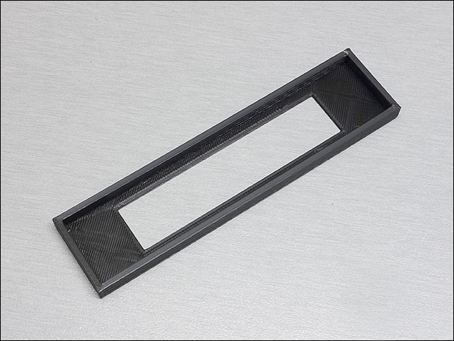
To mount the smalled OLED module in place of the original glass, I designed a 3D-printed support where the OLED module is glued.


The OLED module leaks some light so I used black tape to cover everything but the string of chars. As you can see, the display is smaller but works essentially just like the original one:
You can see the difference side to side between the old display and the new one in this other video:
2023 UPDATE
For years I have replied to those that emailed me asking for more information. I am now getting a lot of requests for the firmware (more than ever) so I am posting below all the information I have. I am not selling the adapter, pre-programmed microcontrolled or OLED modules. Download here.
- Source code for the microcontroller in C
- Compiled .HEX for the PIC 16F88
- My notes on the messages I studied
- The oled module is based on the SSD131x controller (bought in eBay, sadly no longer available)
- STL to 3D print the OLED support that holds it in place of the original display module: